*_ 4 is center between 1 and A . Square backward off points 4, 1, 3, and 2._*
Drawing the Sleeve
Open MacroGen and select Open Project. The folder Designers opens, then open the folder Tutorials MacroGen and select the file Tutorials - Bodice.mg4. This is a sample file included with the MacroGen installation.
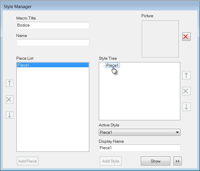
The Style Manager opens.
In the Piece List we have one piece Piece1. The original name Base that appears when starting a new project has been overwritten with Piece1.
To change the name, right-click on it in the Style Tree window or in the Piece List.
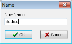
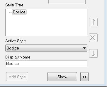
Type in “Bodice” for the new name and click OK. The new name appears in the Piece list, and the piece is also renamed in the Style Tree.
Changing the name of the piece does not change the Display Name (the name that occurs while running the macro in PatternMaker). You also have to change the Display Name into Bodice if necessary. Place the cursor at the name and change it.
We are going to add a sleeve, and it will have styling options which are different from the bodice. That means we need to create a new Piece for it in which we will draw the points and objects of the sleeve.
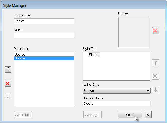
In the Name field type “Sleeve”, then click the “Add Piece” button.
The Piece Sleeve is added to the Piece list. After adding the Sleeve it will be highlighted in the Piece List at the left and therefore also showing in the Style Tree at the right of the Style Manager.
To open the drawing area of the Sleeve click the Show button.
The drawing area of the style option "Sleeve" opens.
When your drawing at the left is not zoomed well in the drawing area, click the Zoom All button in your Status bar. The drawing of the Bodice will be screen filling.
Note: the points and objects of the Bodice appear in blue. This indicates that they were created in another Piece window (in this case, the Bodice). They can be used in this Sleeve window as references for new points, but they can’t be modified here. *
UNITS
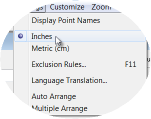
Before we get started, let’s make sure that the Measurement Units are set correctly. These instructions use inches, not centimeters as in the previous tutorials. Click on the Settings menu and see if there is a dot beside “Metric.” If there is, click on “Inches” to change the setting.
-
ONE-PIECE FITTED SLEEVE
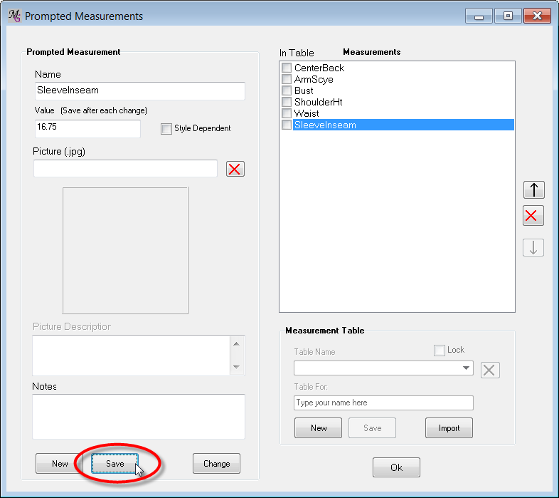
We need to add the Sleeve Inseam measurement (Tab Measure/Add/Prompted Measure).
The instructions tell us this is 16 3/4".
In the Name field "New" appears in blue. Change this into SleeveInseam and enter also the value (type 16.75).
Click the "Save" button and the measure is added and will appear in the Measurements list at the right side of the form.
Exit the form by clicking the OK button.
We enter the points 1 - 26, using the tabbed panel as with the Hood tutorial.
In the small charts, we’ll be using the following abbreviations:
SI |
Sleeve Inseam |
CW |
Clockwise |
CCW |
Counter-Clockwise |
SOL |
Start of line |
EOL |
End of line |
Note that we’re using the prefix “S” to indicate that these points are part of the sleeve pieces.
SLEEVE PART I: DRAFT THE FRAME
We follow the instructions for the Sleeve as mentioned above, described in the book we used for this bodice.
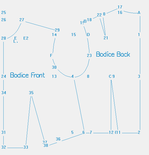
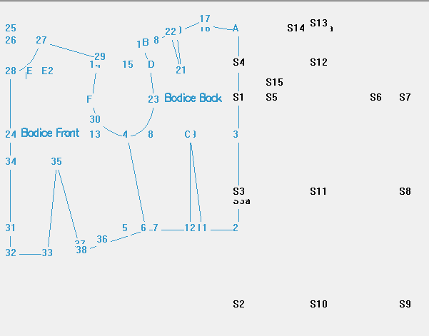
The drawings look like this:

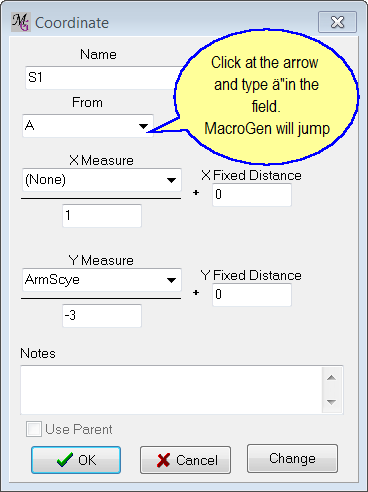
1 from A is full Arm scye on 3rd division.
Pt. Name |
From |
X Meas |
X Scale |
X Fixed |
Y Meas |
Y Scale |
Y Fixed |
S1 |
A |
None |
1 |
0 |
ArmScye |
-3 |
0 |
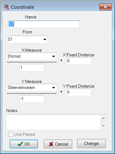
2 from 1 is Sleeve Inseam.
Pt. Name |
From |
X Meas |
X Scale |
X Fixed |
Y Meas |
Y Scale |
Y Fixed |
S2 |
S1 |
None |
1 |
0 |
SI |
-1 |
0 |

3 from 1 is center between 1 and 2 minus 3/4 inch.
Pt. Name |
From |
To |
S3a |
S1 |
S2 |
Pt. Name |
From |
X Meas |
X Scale |
X Fixed |
Y Meas |
Y Scale |
Y Fixed |
S3 |
S3a |
None |
1 |
0 |
None |
1 |
0.75 |
Note: Instead of adding point S3a and S3 you could have added only point S3 Coordinate, From S1, Y meas SleeveInseam, Y scale -2, Y fixed 0.75 *
Pt. Name |
From |
To |
S4 |
S1 |
A |
We can’t draw these “squared-off” lines in MacroGen (unless we create more points and connect them with extra lines), but a benefit of using MacroGen is that we know that the lines are represented by these points, without having to do the extra work.
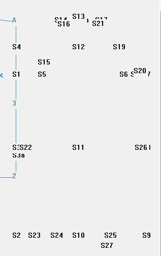
The drawing should now look like this:

SLEEVE PART II: ADD THE SLEEVE POINTS
_ 5 from 1 is full Armscye on 8th division plus 1/2 inch. Square up a short distance toward 15._
ArmScye will be the X Measurement, and the X Scale is “8.”
Pt. Name |
From |
X Meas |
X Scale |
X Fixed |
Y Meas |
Y Scale |
Y Fixed |
S5 |
S1 |
ArmScye |
8 |
0.5 |
None |
1 |
0 |
6 from 5 is full Armscye on 1/2 division.
Again, the X Measure is ArmScye. The X Scale is 2 (armscye divided by 2).
Pt. Name |
From |
X Meas |
X Scale |
X Fixed |
Y Meas |
Y Scale |
Y Fixed |
S6 |
S5 |
ArmScye |
2 |
0 |
None |
1 |
0 |
7 from 6 is full Armscye on 8th division plus 1/4 inch. Square down toward 9.
Here we have an X Offset (0.25” ) used together with the X Measure (ArmScye) and X Scale ( “8” ).
Pt. Name |
From |
X Meas |
X Scale |
X Fixed |
Y Meas |
Y Scale |
Y Fixed |
S7 |
S6 |
ArmScye |
8 |
0.25 |
None |
1 |
0 |
8 falls at intersection of elbow line.
Point 8 is at the same X location (side-to-side) as Point S7, and the same Y location (up-and-down) as the elbow line, represented by Point S3. We can use the Rectangle point type in this circumstance.
Pt. Name |
XCoord |
YCoord |
S8 |
S7 |
S3 |
9 falls at intersection of bottom line.
Again, an intersection of a vertical line and a horizontal line means we can use Rectangle.
Pt. Name |
XCoord |
YCoord |
S9 |
S7 |
S2 |
10 from 9 is center between 2 and 9 plus 1/2 inch.
We can accomplish point 10 in 2 ways. The first way is to use two points, the first point marks the center and the second point is offset from that point like in point S3. Another way is to make a distance measure between S2 and S9 (“Tab Measure/Add/ Distance” )and then a coordinate point using this measure with scale 2 and an X fixed.
M. Name |
From |
To |
S2-S9 |
S2 |
S9 |
Pt. Name |
From |
X Meas |
X Scale |
X Fixed |
Y Meas |
Y Scale |
Y Fixed |
S10 |
S9 |
S2-S9 |
-2 |
-0.5 |
None |
1 |
0 |
Note that the point is calculated from S9, so X Scale and X fixed are minus (to the left).
11 from 8 is same distance as 9 to 10.
Again, an intersection of horizontal and vertical lines is a perfect condition for a Rectangle point.
Pt. Name |
XCoord |
YCoord |
S11 |
S10 |
S8 |
12 falls at intersection of back notch line.
Pt. Name |
XCoord |
YCoord |
S12 |
S11 |
S4 |
13 is 3/8 inch above line A.
Here’s another two-step process. The Rectangle point S13a marks the intersection with the shoulder height line, and then the Coordinate point S13 offsets the point 3/8” above that shoulder line.
Pt. Name |
XCoord |
YCoord |
S13a |
S12 |
A |
Pt. Name |
From |
X Meas |
X Scale |
X Fixed |
Y Meas |
Y Scale |
Y Fixed |
S13 |
S13a |
None |
1 |
0 |
None |
1 |
0.375 |
14 from 13 is full Arm scye on 8th division minus 1/4 inch.
Point 14 needs to be placed on a line from A a certain distance from Point S13. This is a perfect situation for the Line Distance command. The point A defines one point of the line, for the second point of the line we have already S13a. Then we place Point S14 on that line, measuring it from Point 13, Clockwise.
Pt. Name |
SOL |
EOL |
From |
Meas |
Scale |
Fix.dist |
Dir |
S14 |
A |
S13a |
S13 |
ArmScye |
8 |
-0.25 |
CW |
15 from 5 is 1¼ inch
Point S15 is directly above Point S5 (Y fixed distance).
Pt. Name |
From |
X Meas |
X Scale |
X Fixed |
Y Meas |
Y Scale |
Y Fixed |
S15 |
S5 |
None |
1 |
0 |
None |
1 |
1.25 |
Check the status of your drawing:
_16 from 14 is 1/2 inch. Shape run of sleeve head using points 13, 16, 15 and 1 as a guide. _
Point 16 is on the line defined by Point S12 and Point S14. Begin at Point S12, head toward Point S14, then come back toward 12 by the indicated amount (1/2 inch). In other words, you tell the program Go from S12 to S14, and then back up half an inch (=minus).
Pt. Name |
Start |
End |
Meas |
Scale |
Dist |
S16 |
S12 |
S14 |
None |
0 |
-0.5 |
Note: Shaping of the run of the sleeve head by using the points as a guide has to be done different in MacroGen than drafting the pattern by hand. Drawing a curve in PatternMaker is done by drawing an arc and using curve points. Making those curve points we explain later on in this chapter. We have added those points to know over which points the sleeve cap has to be drawn.
17 from 13 is full Arm scye on 8th division plus 1/4 inch.
Point S17 is the same situation as Point S14, except in the opposite direction (counter-clockwise, rather than clockwise as with Point S14, so check the "C-Clockwise" box ).
Pt. Name |
SOL |
EOL |
From |
Meas |
Scale |
Dist |
Dir |
S17 |
A |
S13a |
S13 |
ArmScye |
8 |
0.25 |
CCW |
18 is center between 6 and 7. Connect 11 with 18 and continue line toward 20.
Pt. Name |
From |
To |
S18 |
S6 |
S7 |
19 falls on Line 4.
Point 19 is the intersection point between the lines S4-S12 and S17-S18, therefore a Line Line intersect. A Line Line intersect point can also be placed outside the lines.
Pt. Name |
1 Start |
1 End |
2 Start |
2 End |
S19 |
S4 |
S12 |
S17 |
S18 |
20 from 18 is 1/2 inch.
Pt. Name |
Start |
End |
Meas |
Scale |
Dist |
S20 |
S11 |
S18 |
None |
1 |
0.5 |
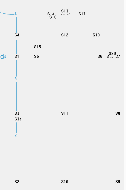
At this point, the drawing should look like this:
21 from 17 is 1/2 inch. Shape cap of sleeve using points 7, 20, 19, 21 and 13 as a guide.
Here, Point S21 is on a line defined by the pre existing points S12 and S17.
Pt. Name |
Start |
End |
Meas |
Scale |
Dist |
S21 |
S12 |
S17 |
None |
1 |
-0.5 |
Note: Shaping the cap of the sleeve by using the points as a guide has to be done different in MacroGen than drafting the pattern by hand. Drawing a curve in PatternMaker is done by drawing an arc and using curve points. Making those curve points we explain later on in this chapter. We have added those points to know over which points the sleeve cap has to be drawn.
22 from 3 is 3/4 inch.
Pt. Name |
From |
X Meas |
X Scale |
X Fixed |
Y Meas |
Y Scale |
Y Fixed |
S22 |
S3 |
None |
1 |
0.75 |
None |
1 |
0 |
23 falls at intersection of bottom line.
Use Line Line Intersect in this case rather than Rectangle because the lines are not perfectly vertical and horizontal.
Pt. Name |
1 Start |
1 End |
2 Start |
2 End |
S23 |
S1 |
S22 |
S2 |
S9 |
24 is center between 23 and 10.
P. Name |
From |
To |
S24 |
S23 |
S10 |
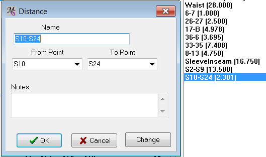
25 from 10 equals same distance as 10 to 24, plus 1 inch.
Create a Distance measure S10-S24 (“Tab Measure/Add/ Distance” ), then use it as the X Measurement for Point S25. Remember to include the 1-inch X Offset.
M. Name |
From |
To |
S10-S24 |
S10 |
S24 |
Pt. Name |
From |
X Meas |
X Scale |
X Fixed |
Y Meas |
Y Scale |
Y Fixed |
S25 |
S10 |
S10-S24 |
1 |
1 |
None |
1 |
0 |
26 from 8 is 3/4 inch.
Pt. Name |
From |
X Meas |
X Scale |
X Fixed |
Y Meas |
Y Scale |
Y Fixed |
S26 |
S8 |
None |
1 |
-0.75 |
None |
1 |
0 |
Connect 26 with 25 and continue line toward 27. Lay long arm of square on 26-25 line, with short arm resting on 10 and square back toward 27.
This tells us that Point S27 is to be the corner of a right angle.
27 falls at intersection of 26-25 line and line 10-27.
The original instructions for point 27 are confusing. Defining Point S27 as an intersection of itself doesn’t make sense. Use the Line Point point type instead of Line Line Intersect. This command does exactly what we need: putting a point at a right angle between a line (S26-S25) and an existing point (S10).
Pt. Name |
SOL |
EOL |
Leg |
S27 |
S26 |
S25 |
S10 |
Now that the points are entered for the shape of the sleeve, the drawing looks like this:
ELBOW DART
28 is center between 11 and 26.
Pt. Name |
From |
To |
S28 |
S11 |
S26 |
Tip:type in the from Field S11 to be able to select this point fast. *
29 from 26 is same distance as 22 to 23 on front sleeve inseam.
Create a Distance measure S22-S23. Then use it as the measurement for Point S29.
Distance measure (S22-S23)
M. Name |
From |
To |
S22-S23 |
S22 |
S23 |
Pt. Name |
Start |
End |
Meas |
Scale |
Dist |
S29 |
S25 |
S26 |
S22-S23 |
-1 |
0 |
30 from 26 is same as 27 to 29, minus 3/8 inch
Create a Distance measure S27-S29, and use it as the Measurement for Point S30.
M. Name |
From |
To |
S27-S29 |
S27 |
S29 |
Pt. Name |
Start |
End |
Meas |
Scale |
Dist |
S30 |
S29 |
S26 |
S27-S29 |
-1 |
0.375 |
Note: the fixed distance is a positive number, because the distance S30-S26 is 3/8 inch smaller as S27-S29 To check if S30 is set right you can add a new distance measure S30-S26
^31 from 28 is same length as 26 to 28.*
Create a Distance measure S26-S28 and use it as the Measurement for Point S31.
M. Name |
From |
To |
S26-S28 |
S26 |
S28 |
Pt. Name |
Start |
End |
Meas |
Scale |
Dist |
S31 |
S30 |
S28 |
S26-S28 |
-1 |
0 |
THE CURVES OF THE SLEEVE CAP
The instructions stop here, but there are more points we need to add in our project to make the curves of the sleeve right. By hand you draw the curves of the sleeve cap going through the added points. But in MacroGen we have to add the corner points at the right place in the pattern and where these corner points need to be placed is not defined in the instructions of the pattern.
There are many ways you can make those curves, it is a matter of how you want to have a sleeve cap drawn (fluently and smooth), of how many curves does it exist and whether you can find the right formulas for placing the curve points at the right place.
The programmed points 16, 21 and 20 can be helpful to test if your curve points are at the right place and if the sleeve cap is going through these points. You can always test everything in PatternMaker to see what you drawing looks like and if you are satisfied.
Note that the pattern making descriptions belonging to your pattern drafting system are always an estimate of through which point the drawing needs to be drawn. To get really smooth fluently going curves it is often necessary to move the point a little bit up, down or to the left or right. It is therefore really important to understand the way curves need to be drawn in PatternMaker to be able to make them in MacroGen.
In this case we add test lines (objects) of the drawn points 16, 21 and 20 to our project. When we test our macro in PatternMaker we can see if our sleeve cap is nearing those test lines.
The best way is making test objects and test the macro in PatternMaker to see if the drawing looks like you wanted it to be.
At the top center of the sleeve cap we see that the sleeve outline goes through Point S13. We divide the sleeve cap in two pieces, the front cap and the back cap with point S13 at the top.
At the front we see in the picture of the sleeve cap a curve (an arc) going from point 1 to point 15. After that we see a curve from 15 - 16 and from 16 to 13. This means 3 curves in a row. The more curves you have in an object the more difficult it is to get it smooth and fluently. Therefore in this case we will make 2 curves at the front :
-
from point 1 -corner(curve) point- point 15
-
from point 15 -corner(curve) point- point 13 (going through point 16).
At the back we see a curve from 7 - 19 through 20 and from 19 - 21 and from 21 - 13. This means also 3 curves in a row. In this case we will make 2 curves at the back:
-
from point 7 -corner point- point 19
-
from 19 -corner point- point 13 (going through point 21).
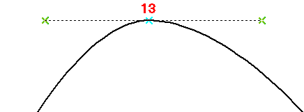
We start with the corner points at the top of the cap. To have a smooth cap head two corner points at the top need to be placed at the same height as point 13, a horizontal line from 13.
A corner point for the front sleeve at the left of 13 and for the back sleeve at the right of 13.
To have two curves fluently going over in each other we can use example 3 in chapter 2: Planning a curve although the two curves here look different, but the system of the corner point-endpoint-corner point in one line is the same.
The question is where should the corner points be placed?
For the front we add a rectangle point 32 with the X of 15 and the Y of 13. The corner point needs to be placed between 13 and 32.
Pt. Name |
XCoord |
YCoord |
S32 |
S15 |
S13 |
To know where the corner point needs to be you could test this in PatternMaker but then you need to make objects form the sleeve points.
Exercise learns that often this corner point is placed at 1/3 of the line 32-13.
This means that a Distance measure has to be made, before you can add this corner point using the distance measure.
M. Name |
From |
To |
S32-S13 |
S32 |
S13 |
We can make the corner point G (since Points A through F were used for corner points in the bodice), again adding the “S” prefix to indicate that it belongs to the sleeve).
Pt. Name |
From |
X Meas |
X Scale |
X Fixed |
Y Meas |
Y Scale |
Y Fixed |
SG |
S32 |
S32-S13 |
3 |
0 |
None |
1 |
0 |
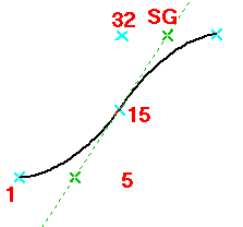
For the front cap we need to add the corner point between the points 1 and 15.
To have two curves fluently drawn example 3 in chapter 2: Planning a curve can be used. The corner point SG - Point S15 and the new corner point are at one line (green cross-blue cross- green cross).
To get this new corner point SH a Line Line Intersect between the points SG - S15 and S1 and S5 is made. In a Line Line Intersect the intersection point can also be placed outside the line.
Pt. Name |
1 Start |
1 End |
2 Start |
2 End |
SH |
SG |
S15 |
S1 |
S5 |
For the back we add a rectangle point 33 with the X of 19 and the Y of 13. The corner point needs to be placed between 13 and 33.
Pt. Name |
XCoord |
YCoord |
S33 |
S19 |
S13 |
We do here the same as at the front: the corner point is placed at 1/3 of the line 33-13.
This means that a Distance measure has to be made,before you can add this corner point using the distance measure.
M. Name |
From |
To |
S33-S13 |
S33 |
S13 |
Now we can make the corner point SI.
Pt. Name |
From |
X Meas |
X Scale |
X Fixed |
Y Meas |
Y Scale |
Y Fixed |
SI |
S33 |
S33-S13 |
3 |
0 |
None |
1 |
0 |
For the back cap we need to add the corner point between the points 7 and 19.
Using point 18 for that as a corner point will not give a fluently drawn curve, because the points GI -19 - 18 will not be on one straight line
We make another Line Line Intersect between the points SI - S19 and S7 - S6.
Pt. Name |
1 Start |
1 End |
2 Start |
2 End |
SJ |
SI |
S19 |
S7 |
S6 |
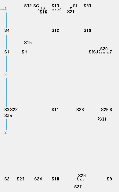
The current drawing with all points added:
CREATE SLEEVE OBJECT
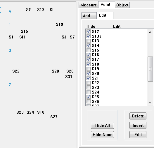
(Note: before you begin connecting points, you may wish to hide the points not used to create the sleeve. To do this, select Point and Display/Edit from the tabbed panel, and hide ONLY the points in the list below by checking the boxes next to them. Then, beginning at the top of the point list and going straight down, click each box — this will hide all of the points you don’t need to see, and show all of the ones that you DO.)
Here, only the points used in connecting the object are shown:
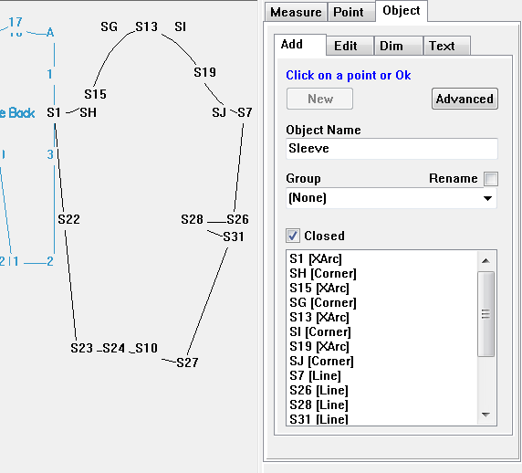
Now we can add the new object Sleeve.
Using the panel, select the tab Object/Add, and click the New button. In the Object Name box, type "Sleeve". Connect the points by clicking on them in the following order
Remember that you need to LEFT-click on a coordinate before you can right-click to change it to XArc Start (X) or XArc Corner ©
S1 |
X |
SH |
C |
S15 |
X |
SG |
C |
S13 |
X |
SI |
C |
S19 |
X |
SJ |
C |
S7 |
L |
S26 |
L |
S28 |
L |
S31 |
L |
S27 |
X |
S10 |
C |
S24 |
L |
S23 |
L |
S22 |
L |
Closed |
Checked |
The Sleeve object is saved now.
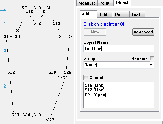
To check if the sleeve cap is going over the original drawn points S16 and S21 we make a test line of them. When we test the macro in PatternMaker we can see the result.
At first before we can add that test line we have to make the points visible. So select the Point tab and make the points S12, S16 and S21 visible by unchecking the Hide checkbox.
Then select the tab Object Add, and click the "New" button. In the Object Name box, type "Test line". Connect the points by clicking on them in the following order:
S16 L- S12 L- S21L and leave the object open. Click OK to save the Test line.
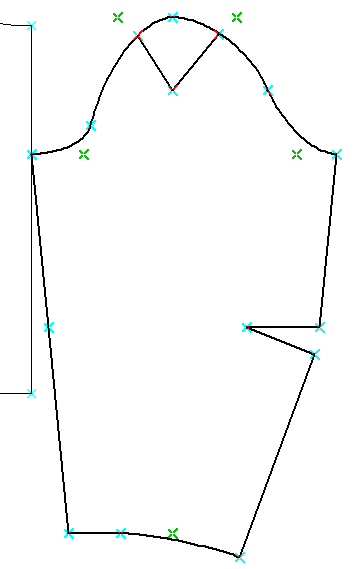
Now we can test the macro in PatternMaker to see if the sleeve cap is drawn all right, so click the Test Macro button and PatternMaker will be launched. The drawing of the sleeve is shown at the right side. The sleeve cap is going nicely over the Test line with the points 16 and 21. This means that our formulas where to place the corner points were right. You could also test if this is going well with other measurements. To see if the sleeve cap is also drawn right over point S18 you could make another test line for it.
If you don’t like the shape of this sleeve, you can change the position of some points if you wish. However, keep in mind that this is simply an exercise in MacroGen commands, not pattern drafting technique. When you use your own drafting system, sleeves and all other pieces will look much more familiar to you.
When you are satisfied with the form of your sleeve you can delete the test lines. You do not want them further appearing in your macro or drawing.
We have two different Pieces – Bodice and Sleeve – we are going to add styling modifications to them.
Close this editing window and go back to the Style Manager.
Save your new file with the name “BodiceWithSleeve.mg4" (use Save as)