Drafting a Hood
For the first tutorial we will be following a set of drafting instructions written by Finnish designer Leena Lähteenmäki. These instructions are provided in the following pages. You may find it helpful to refer to the original instructions as you work through this tutorial; however, this is not an exercise in how to translate written instructions to MacroGen commands. (We’ll get to that a little later in Tutorial 2.)
This tutorial will introduce you to: * the MacroGen environment * the main features of the program * the most important commands to begin your own project.
These instructions in Tutorial 1 will tell you: * the steps to follow * how to do them.
We do not focus on why to do them. We just want to get you up and running with MacroGen, and let you see how easy it is to use.
If you want more explanation on the commands themselves, find detailed information in the Help file.
Begining a new project
We assume you have successfully installed MacroGen from the PatternMaker CD or download.
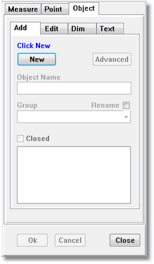
When you start MacroGen you will see this dialog box
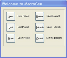
Click “New” to begin a new project
The Style Manager opens. On the left side it lists all the pieces the macro will create. A Base piece is already there.
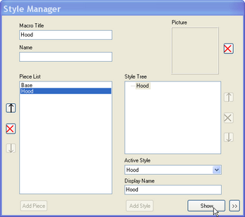
Type “Hood” in the “Macro Title” field. Type "Hood" in the Name field and click the “Add Piece” button.The word "Hood" appears in the piece list on the left.
The Piece that is highlighted on the left will appear on the right side under the Style Tree.
it is possible to make more style options to this Piece. (In PatternMaker while running the macro you will get a style form with the style options to choose from.)
Highlight "Hood" under Style Tree
Click the "Show” button.
(Note: In MacroGen, a "Piece" can consist of more than one drawing object. For example, a “Piece” may be an entire pair of pants, with the individual pattern pieces (front, back, facings, waistband) being different drawing objects in the same Piece window.) For simplicity, in this first tutorial the hood will be a single object.)
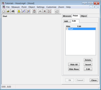
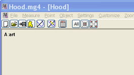
A blank editing window opens, the Pattern Area.
On the left you see the area where the pattern will be drafted, beginning from the Start point.
On the right side a Tab panel with the tabs Measure, Point and Object is showing.
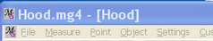
In the title bar you can read which file (if saved) and style have been opened (Tutorials - Hood.mg4 file and .[Hood] style.)
Save your file with the name "Tutorials - Hood" by using the Save icon.
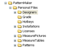
Automatically a Designers folder in My documents/PatternMaker/Personal files will open, where all MacroGen projects can be saved.
Note: You will find examples of all the tutorial files in the folder Tutorials.
THE MACROGEN ENVIRONMENT
Let’s take a look around here for a moment.
The main window takes up most of the space, with a tabbed panel to the right. There is a standard file menu along the top, with a row of buttons underneath. All of the design functions are available in the tabbed panel, and every command is available from the menu.
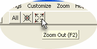
You can zoom in and out by using the commands on the Zoom menu.
SET THE MEASUREMENT UNITS
Before we do anything, we need to tell MacroGen we will be working in centimeters. For your own projects, you can use either inches or centimeters, but since we will be working along with Leena’s instructions, we will use centimeters throughout all these tutorials.
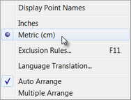
On the Settings menu (the upper menu, not the panel), click the word “Metric” so that it is clearly selected.
Select: Settings/ Metric
Okay, now we’re in metric. Let’s move on.
SET THE DEFAULT MEASUREMENTS
The first main step in designing your new macro is to define the default measurements that the user will be asked for as the macro is run. The macro will take these inputs, put them into equations that you’ve set up, and then draw the objects that result.
Select from the tab panel the tab Measure / Add / Prompted Measure
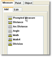
A form appears with the title "Prompted Measurements".
Create a measurement called "Neck" (neck circumference) and give it a default value of 33.5
Measure Name Neck Value 33.5 Click "Picture" edit field
A windows browser form appears and the folder MeasurePictures opens. You can scroll to the folder Tutorials where all files for the Tutorials are saved. (My documents/PatternMaker/Personal files/Designers)
Select file "Hood Width.jpg"(you can only select .jpg files with a maximum of 400x400 pixels)
Click the "New" button on the left side.
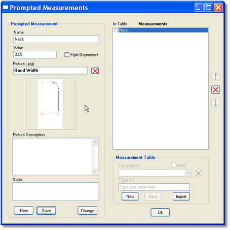
Note: By clicking the New button you just added the measurement to the Measurements list at the right side. It will also appear later on in the Measure/Edit list, with the default value (33.5) in parentheses.
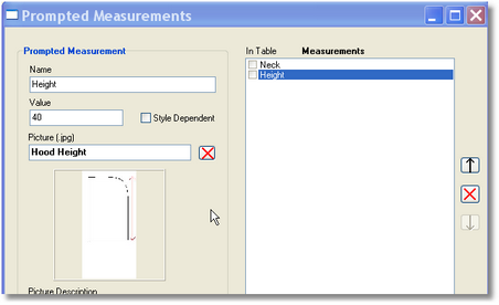
In the name field "New" is appearing. Overwrite this with the name of the second measurement called "Height" (height of hood). Give it a default value of 40.
Measure Name Height Value 40
Click "Picture" edit field Select file "Hood Height.jpg" in the folder Tutorials
Click the "Save" button and then the Ok button.
Note: don’t worry about the "Measurements Table field in this form. It will be covered in a later tutorial.
Both measurements are saved now, and you will be returned to the Piece window. The Piece window is where you will see the points for the hood appear as you create them. Right now the hood only has one point, named Start.
In the title bar of this window you can see which piece/style is opened. At the moment the piece [Hood] is opened from the file Hood.mg4 .
ENTERING NEW POINTS
Now that we have some default measurements, we can start entering points. The first point we create will be of the “Coordinate” type.
A point created with the Coordinate Point method (short for Coordinates) is always measured from one single other point. You determine a reference point (the From point) and then tell MacroGen how far away the new point is and in what direction. If the From Point’s location is changed (usually because the user entered different measurements which moved it), this dependent point will be changed, also.
A BRIEF DIVERSION
If you need to visualize what’s happening here, imagine a grid with an X axis (horizontal measurement) and a Y axis (vertical measurement). The point you are measuring from is always at the center of the grid, at the intersection of the X axis and the Y axis. This is similar to working with gridded pattern paper. You use the grid to keep lines straight, but also to determine how far one point is from another.
Sometimes you will know exactly how far apart two points are (“Point B is always 2cm from Point A”). This is a fixed distance. No matter what body measurements the user enters, Point B will always be 2cm from Point A.
 At other times, you will not have a specific number in mind. You may know only that the distance from Point A to Point B is equal to some body measurement – the arm length, the center back length, the neck circumference, etc. This will be different for each person who uses your macro. In this circumstance you cannot use a fixed number. You must use a variable.
The location of a new Coordinate point is always relative to its From Point, modified by the values you enter. If you use the Offset fields, the distance will be fixed – the point is always “offset” by such-and-such amount. If you use the X-Measure and Y-Measure fields, the distance will be variable – based on the measurements input by the user.
The Scale values let you use fractions or multiples of the measurements. It is the number the Measurement is divided by. For example, if you select “Waist Circumference” for your Measurement, and set a Scale of 4, the user’s waist measurement is divided by four. (That is, one-quarter the user’s waist measurement.)
You can read more about Offsets, Measurements and the Scale feature in the MacroGen Help file.
BACK TO ENTERING POINTS…
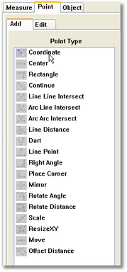
From the Tab panel select the Point Tab, select Add / Coordinate The Add / Edit coordinate point form opens.
The first point added will be called A. Point A will be located at the Start point (X and Y offsets of 0).

Note: It is better that the Start point is not part of the drawing. This can cause problems later with Editing in PM. Therefore we make a new first point from which we draw other points (you could also give in an X and Y offset from Start).
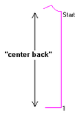
Follow the illustration to the left and enter the following information:
Name |
A |
From |
Start |
X Fixed Distance |
0 |
Y Fixed Distance |
0 |
Click "OK".
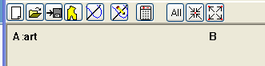
In the piece window, Point A is located right on top of point Start.
If you don’t see your new "A" point, click the "All" button at the top.
Note: Use the X and Y "Fixed Distance" boxes to fine-tune the placement of your coordinates
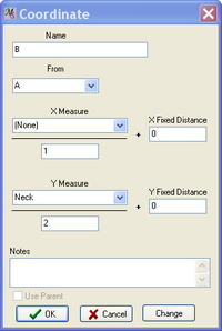
We’re going to draft a rectangle whose width is 1/2 the neck measurement, so let’s mark out this distance: Add another Coordinate Point (Select “Add/Coord” from the Point tab). This point will be measured from Point A. The distance of Point B from Point A is equal to the measurement "Neck" with a Scale of 2 (“Neck” divided by 2). Since this is a variable, use the Measure fields rather than the Fixed Distance fields:
Name |
B |
From |
A |
Y Measure |
Neck |
Y Scale |
2 |
Click “OK”.
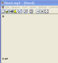
Now point B appears in the piece window:
Comparing this result with our drafting instructions, it’s clear right away that we’ve made a mistake. Point B is supposed to be directly to the right of Point A, not above it. What happened?
We filled in the Y measure while it supposed to be the X measure.
CORRECTING A MISTAKE
If you find you’ve made a mistake in entering a point, there’s an easy way to correct it. Click on the point in the display to bring up the Coordinate window of point B, where you can make the necessary changes.
Y Measure |
(None) |
X Measure |
Neck |
X Scale: |
1 |
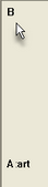
Click “OK”. Now Point B appears in its proper place:
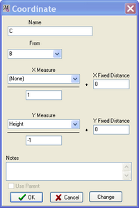
Add another Coordinate Point (Point/Add/Coordinate). Point C marks the height of the rectangle, so it’s measured from point B in a vertical (Y instead of X) direction. The scale factor of -1 means the direction in which it is measured is reversed (down instead of up).
Name |
C |
From |
B |
Y Measure |
Height |
Y Scale |
-1 |
Click the “OK” button.
RESIZING THE PIECE WINDOW
Depending on the size of your piece window, you may not be able to see all of the points you just entered.

Try adjusting your zoom level with the buttons.
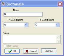
Now we’ll enter Point D to complete the rectangle. To create it, we’ll use a Rectangle point instead of Coordinate. Choose Point Tab / Add / Rectangle. The Rectangle point type means that no matter where points A and C are placed, D will automatically be put at the corner of the rectangle they define:
Name |
D |
X-Coordinate |
A |
Y-Coordinate |
C |
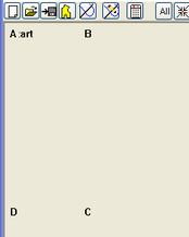
Your drawing should now look like the illustration below. If it does not, remember that you can edit a point by pointing at it and clicking when the cursor turns to a hand.
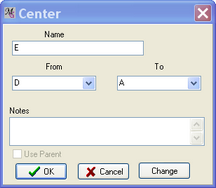
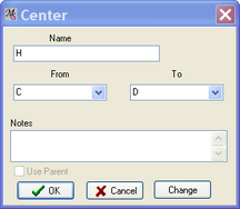
Point E marks a point halfway down the rectangle. Add a point midway between A and D (Point/Add/Center). A Center point will always be placed halfway between the two points it’s based on.
Name |
E |
From |
D |
To |
A |
ALTERNATE WAYS OF SELECTING COMMANDS
All MacroGen commands can be selected in two ways: menus and the tabbed panel. The tabs on the panel correspond to the commands on the pull-down menus and are specific designed for an easy use of managing the points, measure and objects commands.
In the instructions so far, you’ve been instructed to select commands from the tab menus for getting to work with the tab panel.
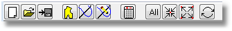
If you can’t remember what a particular icon (button) is for, just point at it with your mouse. A yellow ToolTip pops up at the cursor location, and a longer description is displayed in the message bar at the bottom of the main MacroGen window.
As you can see in the menu and in the ToolTip example above, some commands also have a Hot Key assigned to them. Hot Keys are assigned to the most commonly-used commands. You can use whichever selection method feels most convenient to you.
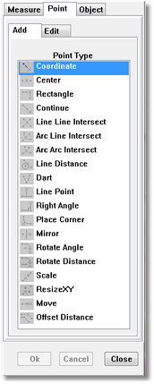
Click the "Point tab in the tabbed panel, and then click the "Add" tab
From here, you can simply select the option you want by clickin on the appropriate icon in the list.
Select "Coordinate" from the list and continue on.
ENTER REMAINING POINTS
Point F marks where the curve at the back of the hood begins. It will always be the same distance from point B ( *Point*N / *Add / Coordinate ), so use a Fixed Distance value:
Name |
F |
From |
B |
X Fixed Distance |
-8 |

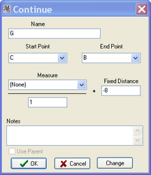
Point G marks the other end of the curved section. It lies on a line from C to B, 8 cm from B. The "Continue" point type puts a new point on a line drawn through any two existing points. A negative Fixed Distance means that you begin at the start point and head toward the end point (moving in a “positive” direction), and then when you reach the end point, come back in a “negative” direction for a certain distance. (By contrast, in other circumstances you might continue to move in a positive direction from the start point past the end point to the destination.) In this case, the location of Point G is determined by beginning at Point C, heading toward Point B, then reversing 8cm (a “negative” distance) on that line to arrive at Point G. (Read more about the Continue point type in the Help file.)
Name |
G |
Start |
C |
End |
B |
Fixed Distance |
-8 |
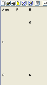
Notice that we’ve just used two different methods (Coordinate and
Continue) to do practically the same thing with points F and G.
In this situation, either one works.
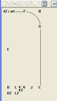
Your drawing should now look like this:
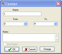
Points H, J, K, and *L8 will mark out a curved line at the bottom of the hood. The width of the hood is divided into halves, quarters, and eighths, so we’ll use the Center point type repeatedly:
Name |
H |
From |
C |
To |
D |

Name |
J |
From |
C |
To |
H |
Name |
L |
From |
D |
To |
H |

Name |
K |
From |
L |
To |
H |
Check that your drawing is correct to this point:
The original instructions tell us to move Point A 2 cm away from the rectangle. MacroGen doesn’t move a point after it’s already been used, so instead we’ll define a new point and call it A2:
Name |
A2 |
From |
A |
X Fixed Distance |
-2 |
Note: When the list of points to choose from is longer you can scroll to the right point to select it or just type in the point name and MacroGen will jump to it in the list.

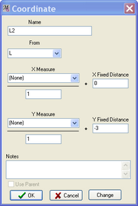
We also need to place points D2, K2, and L2 on a curve below the bottom of the hood. These points are based on D, K, and L. (In other words, points A, D, K, and L aren’t really part of the pattern. They are intermediate values used as part of a two-step process to calculate the actual points needed. When you get into a situation where a point’s location requires a complicated calculation, there will usually be more than one way to translate the original drafting instructions to the MacroGen tools. There is no particular "right" method.)
You will notice later that although points A, D, K, and L appear in the object window, they won’t be used to create objects and therefore won’t be seen in the final pattern.

Name: |
D2 |
From: |
D |
Y Fixed Distance |
-3 |
Name |
L2 |
From |
L |
Y Fixed Distance |
-3 |

Name |
K2 |
From |
K |
Y Fixed Distance |
-1.5 |
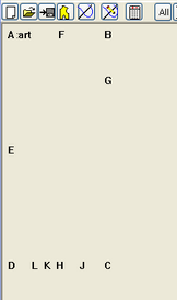
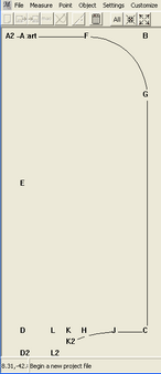
CHECK ALL THE POINTS
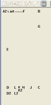
Now we’ve finished entering all the points that will make up the hood. Check that your drawing looks like the illustration below:
Remember that you can use Zoom All (Ctrl+A) or click the "All" button if some of the points are outside the viewing area.
You can also scroll with the mouse wheel to zoom in or out.
CONNECT THE DOTS
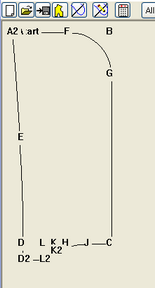
As you’re adding points, the editing window doesn’t show an actual drawing object (a pattern piece). What you see is only a representative view of the points that can then be used to draw the hood. Now it’s time to create an object, and tell MacroGen what points to use. This is a little bit like a connect-the-dots puzzle.
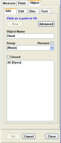
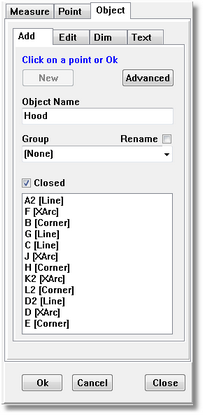
Select Object / Add from the Tab panel Click the "New" button Type " Hood" under "Object Name"

Now, in the main window, left click on the point A2. We will write this dow as:
-
A2 Left Mouse
In the point list you’ll notice that A2 is added. You can’t tell yet, but you have begun a line.
Add the rest of the points:
-
F Left Mouse
-
B Left Mouse
-
G Left Mouse
-
C Left Mouse
Add Points
-
F Left Mouse
-
B Left Mouse
-
G Left Mouse
-
C Left Mouse
Changing a point type
We’ve made another deliberate mistake. The section from point F to Point G should be an arc, not a square corner. We need to change point F to type Arc.
Double-click F on the screen or in the panel list
The Connection box comes up:
-
Select XArc Start
-
Click OK
In the list after F [ XArc] will appear

You choose XArc Start, because point F is where your first arc (curve) begins.
MacroGen changes automatically point B in a Cornerpoint.
In the list you will see B [Corner]
Note:
You also can click on point B and choose for XArc Corner. Point F would have been changed into an XArc Start point
(That’s better.)
The next point J is the start of an arc rather than a simple line.
First:
-
J Left Mouse
-
H Left Mouse
Now, double-click on J again (on the screen or in the list) to bring up the Connection Box, and select XArc Start.
The next point after the start point of an arc is automatically a corner point. Don’t worry that you didn’t see anything happen when you clicked on it, or if you see the line section disappear. When you add the next point, the whole arc will appear. Click OK to exit the form
-
K2 Left Mouse
Click RM now or Double-click K2 in the panel to open the Connection form and change the type to XArc Start.
-
E Left Mouse
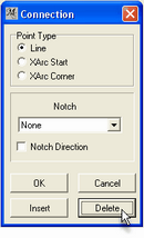
Deleting a point from an object
This is another mistake. To delete E, bring up the Connection Box, so doubleclick at point E on the screen or in the list of points.
(E should be the corner point of an arc that begins at D (not D2) and ends at A2, the start point of the object.)
-
E doubleclick Left Mouse (Connection box opens)
-
Select: Delete - OK
-
L2 Left Mouse
-
D2 Left Mouse
-
D Left Mouse
Now we are changing point D into a XArcStart point
-
D Right Mouse or double-click LM (in the main window or in the points list)
-
Select XArc Start - OK
-
E Left Mouse (will be a XArcCorner point)
Click the "Closed" checkbox in the Object tab. When the Closed checkbox is checked, MacroGen closes the object by connecting its first and last points.
You’re done making the Hood object.
The OK button in the tabbed panel completes the job.
-
Click: OK
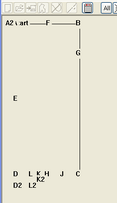
Now the object is finished.
When you forget to click OK or Cancel after adding or editing an object MacroGen will give you a message to click OK or Cancel.
Hiding/Displaying points
Having too many points showing on screen together can interfere with your work. Points can be switched off selectively, which makes the object appear less cluttered.
With Points Tab
Bring up the panel again and click the "Point" tabs and select "Edit".
You can hide every point on the drawing screen by checking the hide box in the display list of points.
Check the following points:
-
Start
-
A
-
J
-
L
-
K
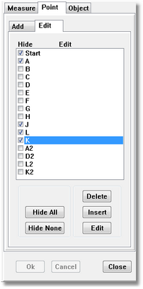
check the Hide box to hide a point on the screen
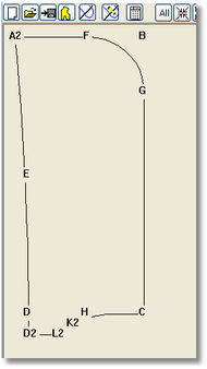
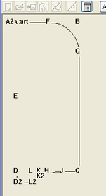
Your drawing displays only the points that are actually used in the hood object.
Clicking the Hide All or Hide None buttons will hide all points on the screen or display all points at once.
A different way of showing of hiding the points can be done in the Object Tab.
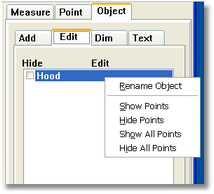
To see only these points that are used in the Hood object go to the Tab Object and select the Edit Tab.
Select with LM the Hood object in the list and click RM.
A right mouse menu appears to choose from several options:
-
Rename the object
-
Show Points used in this object
-
Hide the points used in this object
-
Show all points made in this style
-
Hide all points made in this style
SAVE THE FILE AND CONVERT TO A MACRO
Save your file once more with the Save File icon in the Status bar.
The file will be automatically saved in the folder Designers in My
documents/PatternMaker/Personal Files
You can add here sub folders if you want.
We have added a sub folder Tutorials where you will find all the MacroGen example files of the Help and Tutorials.

Create Macro
Now that your MacroGen project has all the logic set up, you can create a macro from it using the Create Macro Icon (as in PatternMaker).
or File/Create Macro.
You won’t see anything visible happen when you do this. However, in the background, MacroGen has created a macro file based on the same name as your project file (and saved it in the same directory) .
You have just created a macro (Tutorial - Hood.MAC) file.
Test macro
To test this macro you can start PatternMaker from MacroGen with the Test Macro Icon and see the results:
or select “Test Macro in PatternMaker” from the File menu.
PatternMaker will launch and automatically run the Hood macro.
See how the hood is drawn with the default measurements.
Close PatternMaker (do not save changes) to return to MacroGen.
If you wish, repeat the test as above, but type different numbers into the measurements dialog box when it appears. Compare to the first version of the hood pattern.
Close PatternMaker again, and do not save changes.
You will automatically return to MacroGen
Continue on to Tutorial 2 to learn how to translate written drafting instructions into MacroGen!