image:3_045_Point25.png[alt=""]
Drafting Ladies' Pants
For this tutorial we will again be following the set of drafting instructions written by Finnish designer Leena Lähteenmäki that we already explained in Tutorial 2
In this Tutorial 2, we worked through the drafting instructions and created an “outline” of the points we were going to add into MacroGen. Now we are ready to actually enter the points and create the macro for ladies’ pants.
SETTING UP THE BASICS
Open MacroGen. Click the New button (Begin a new project). The Style Manager automatically opens.
Check Settings on the menu to make sure you have it set to Metric.
CREATE A PANTS PIECE AND DISPLAY IT
In the Macro Title field, type Ladies Pants. This is the text that will appear in the measurements dialog box when the macro is run.
In the New Piece Name field, type Ladies Pants again, and then click the Add button.
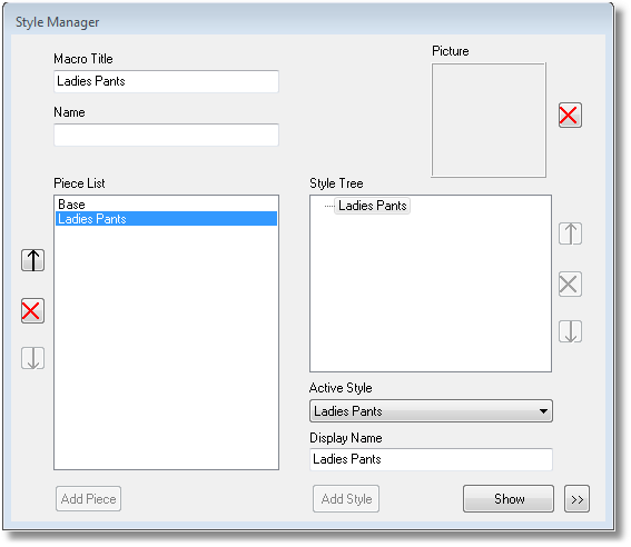
Macro Title: Ladies Pants New Piece Name: Ladies Pants Click: Add
Highlight Ladies Pants under Style Tree (the Piece Base is a default piece which is empty. You can overwrite this piece with your own name.)
Click the Show button
A blank editing window opens, with a tabbed panel on the right.
ENTER PROMPTED MEASUREMENTS
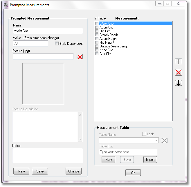
From the tabbed panel from the top row of tabs, select Measure, and then Add from the side row of tabs. Click Prompted Measure (you can also select Measure/Add/Prompted Measure from the menu).
The Prompted measurements form appears. Enter the Body Measurements. We call them prompted because when running the macro they are asked to fill in. Give each one a name and a default value. Click at the left side the New button to save this measure and enter the next one. Remember that we’re estimating on Knee Circumference and Cuff Circumference.
Click the "Save” button after you have entered the last measure Cuff Circ .
Click the OK button to close the prompted measure window
Measure / Add / Prompted Measure
Measure Name |
Default value |
Waist Circ |
78 |
Abdm Circ |
95 |
Hip Circ |
102 |
Crotch Depth |
27.5 |
Abdm Height |
9 |
Hip Height |
19 |
Outside Seam Length |
105 |
Knee Circ |
54 |
Cuff Circ |
40 |
If you misspell one of your measures, or you want to change a default measurement, click the measure on the right side in the list so it is selected and the name appears at the left side. Make your change and click Save again. You can also select the measure through Measure/Edit and then select the measure from the list. *
SETTING CALCULATION RULES
In Part A, we made some notes on certain body measurements that must be modified in order to use them in the macro – specifically, the waist and hip circumference measurements. Now we need to tell MacroGen how to modify them and under what circumstances.
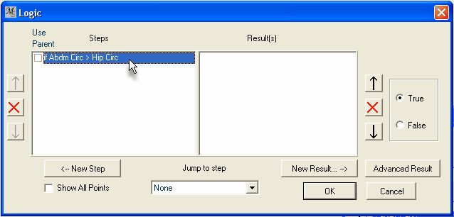
Using the menu, select Point/Logic.
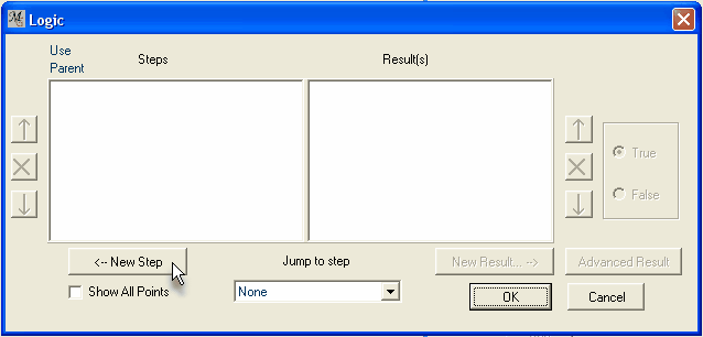
In this Logic form, we can define certain If conditions that MacroGen will check for. Use this feature to add flexibility to your designs. For example, you might create a rule that says, If the person’s bust circumference is between X and Y, then the neckline depth equals this; if the bust circumference is between Y and Z, then the neckline depth equals that. The Steps window displays the If conditions, while the Result(s) window shows the end result.
For now, we will add the conditions that Leena’s instructions have laid out for us:
Rule 1:
If your abdomen circumference is larger than your hip circumference, use it for your hip circumference.
Set the IF condition:
-
Click on the “New Step” button. The Step form opens.
-
Click: New Step
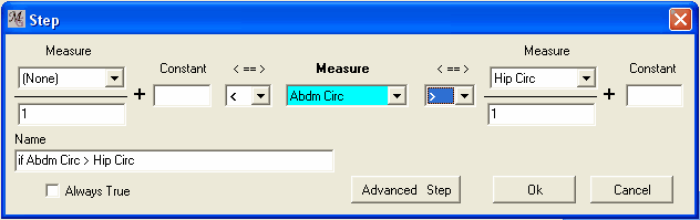
This form is read from the center outward (blue highlighted measure):
(IF) [a measurement] is [greater than/less than/equal to] [another measurement]…
Select Abdm Circ from the drop-down list in the center of the form.
Select " > " (“greater than”) from the ⇐⇒ drop down list right of Abdm.Circ.
Select Hip Circ from the Measure drop-down list at the far right of the form.
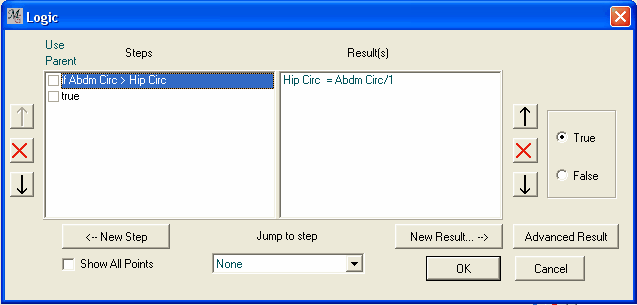
The formula you filled in will appear as the name of the step ( if Abdm Circ > Hip Circ ) in the Name field.
Condition: if Abdm Circ > Hip Circ
Leave the rest of the fields on this form the way they are for now, and click the “OK” button to return to the Logic form.
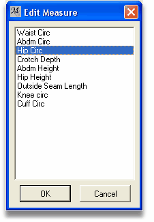
To set the THAN result: Highlight “Abdm Circ > Hip Circ”. Click on the “New Result…” button.
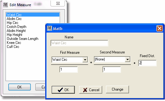
The Edit Measure form appears; Search for the Hip Circ measure and double-click it The Math form of the Hip Circ measure opens:
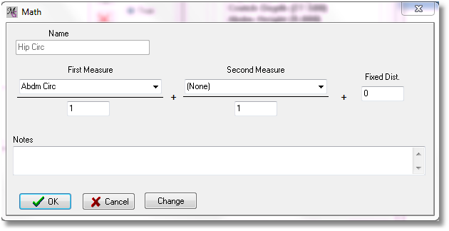
Since Hip Circ has been selected as the starting point for the new result, it appears first, under "Name". Now, set "First Measure" to Abdm Circ. So, this result is saying: "Hip Circ = Abdm Circ." (In the graphic above, there is no second measure or additional number (constant) added for now).
Click OK to return to the Logic form (picture down).
Now that the result shows up in the Result window, the form can be read from left to right as: If Abdm Circ is greater than Hip Circ, then Hip Circ equals Abdm Circ. All that does is to replace the user’s Abdm Circ measurement with the hip measurement IF the Abdm Circ measurement is larger.
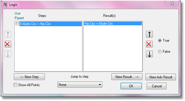
Click OK. Next, select Point/Logic from the menu once again:
Rule 2
Add 2 cm ease to the waist circumference measurement.
Rule 3
Add 4 cm ease to the hip circumference measurement.
(Note that there is no IF in these rules. They’re saying always add ease to the waist and hip measurements.)
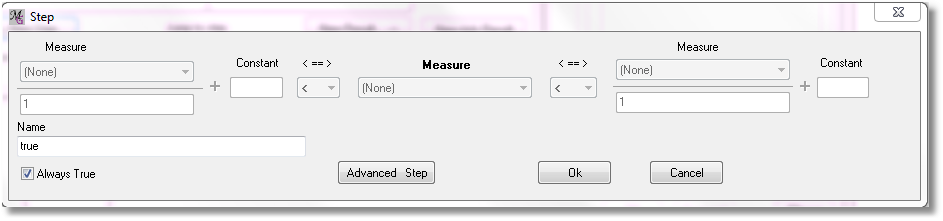
Click on the New Step button.
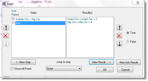
Check the Always True check box In the name field True will appear (when there is already a true step it will be True(1) etc.
All the other boxes will gray out.
This indicates that whatever you enter in the corresponding Results form will be carried out under any circumstances - in other words, two centimeters will ALWAYS be added to the measurement the user enters.
Leave the other fields blank. Click the OK button to return to the Logic form.
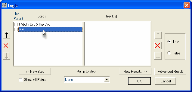
Highlight the “true” entry in the “Steps” list (and notice the radio button at the right side is set to “true”).
if the condition “true” appears first in the list and you want it to appear second, you can use the down arrow on the left to change its position.
With true highlighted, click the New Result button. The Edit measure form opens.
Select Waist Circ. from the list and click OK or double click Waist Circ. in the list.
Here you are defining a rule that will always be carried out: “Set the Waist Circ measurement to the existing Waist Circ + 2 cm.”
So now, enter "2" as your Fixed Distance, and click OK to return to the Logic form.
Note: If your design required it, you could add two Measurements together using this same method. For example, if your measuring system takes separate Front Waist and Back Waist measurements, you could define a rule that says, "Waist Circ equals Front Waist + Back Waist". If you wanted to do that and add ease all in one step, you would again enter the "2" in the field at the far right.
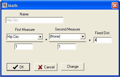
With the “True” condition still highlighted, click on the “New Result” button to repeat the previous steps, this time specifying Hip Circ.
Enter "4" as your constant (Fixed Distance), and click OK to return to the Logic form.
There are now two Results listed which correspond to the “True” Condition.
Note: The result(s) column only displays the results that correspond to the highlighted Condition. If you don’t have "true" highlighted in the above illustration, you’ll see a different set of results
Click on the first Condition in the list. Notice that the Results list changes.
Note: MacroGen carries out the rules in the Calculation Rules form in the order in which they appear. This order is important. Here, we compare Hip Circ and Abdm Circ (the first condition we created) before we add 4 cm to Hip Circ
Click the OK button to return to the main window.
ENTERING THE POINTS to Draft the frame
Using the tabbed panel, click Point and Add. Click on Coordinate (at the top of the list).
This is the Coordinate form, which we learned about in Tutorial 1. Follow your notes from Lesson 2 and enter the numbers in the appropriate fields.
When the Start point is a part of our drawing, this could cause problems later on with editing the drawing. Therefore, we first create a new first point a couple of cm offset to Start.
Name: |
S |
From: |
Start |
X Fixed: |
5 |
Here, the first point in your drawing will be point S, drawn 5 cm to the right from Start. From here you start to draw the other points.

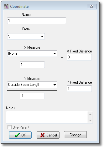
Name |
1 |
From |
S |
Y Measure |
Outside Seam Length |
Y Scale |
-1 |
Y Fixed |
1 |
Here, you have created the line for Outside Seam Length (Point 1): Next, create the Abdomen Line (Point 2):
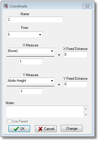
Name |
2 |
From |
S |
Y Measure |
Abdm Height |
Y Scale |
-1 |
Y Fixed |
0 |
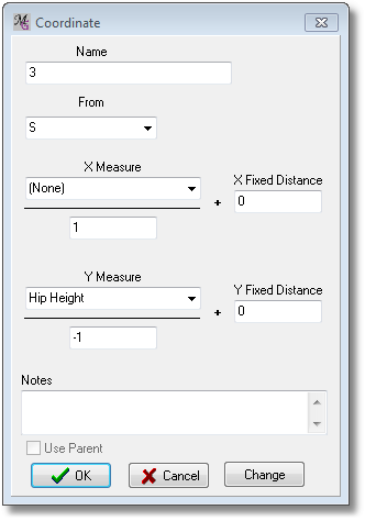
Create Hip Line (Point 3):
Name |
3 |
From |
S |
X Fixed |
0 |
Y Measure |
Hip Height |
Y Scale |
-1 |
Y Fixed |
0 |
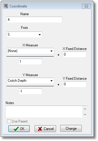
Create Crotch Line (Point 4):
Name |
4 |
From |
S |
Y Measure |
Crotch Depth |
Y Scale |
-1 |
Y Fixed |
0 |
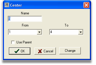
Find crotch-cuff midpoint (Point 5). For this we will use the CENTER point type.
Again, follow your notes from Lesson 2:
Name |
5 |
First Point |
1 |
Second Point |
4 |
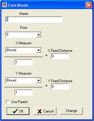
6 cm up from Point 5 is the Knee Line (Point 6) :
Name |
6 |
From |
5 |
Y Measure |
(None) |
Y Fixed |
6 |
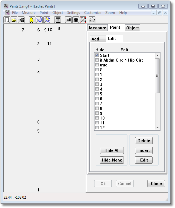
Check your drawing at this point and make sure that your points are in the right places:
Click the Zoom All button to make all the points on screen visible.
Point Start is hided here, see the checkbox
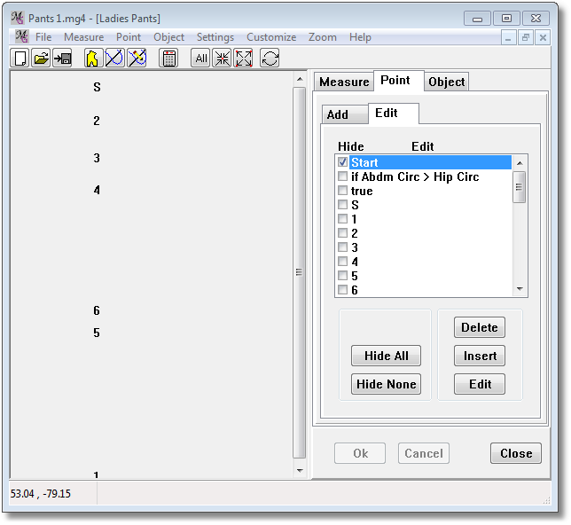
Tip: With checking the Hide box in the Point/Edit list you can hide points on the screen or make them visible. With the Hide All/Hide None button you hide/show them all at once.
ENTER POINTS FOR PANTS FRONT
Divide the Waist Circ by 8 (Point 7) and mark it to the left (“negative” direction) of Start. This is the waist center front point:
Name |
7 |
From |
S |
X Measure |
Waist Circ |
X Scale |
-8 |

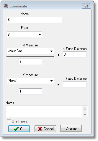
Mark the point to the right (Point 8). This is the waist side front point.
Remember, the Scale divides Waist Circ by 8, and the X Offset and Y Offset of “3” and “1” respectively put Point 8 a additional 3cm further to the right and 1cm up.
Name |
8 |
From |
S |
X Measure |
Waist Circ |
X Scale |
8 |
X Fixed |
3 |
Y Fixed |
1 |
Find the dart start point. This is 4.5 cm from the center (horizontal or X direction), on the waist line (vertical or Y direction):
Name |
9 |
From |
S |
X Measure |
(None) |
X Fixed |
4.5 |

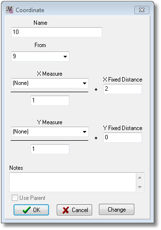
Create the point on the other side of the dart (Point 10) :
Name |
10 |
From |
9 |
X Measure |
(None) |
X Fixed |
2 |
Create the dart apex (Point 11).
We use the Rectangle point type because Point 11 is the same position left-to-right as Point 10, and the same position up and-down as the abdomen line (represented by Point 2):
Name |
11 |
X-Intersect |
10 |
Y-Intersect |
2 |

Adding a New Measurement
Notice that one side of the dart (between Point 9 and Point 11) is longer than the other (Points 10 and 11). Both sides of the dart need to be the same length, so that the dart can be sewn closed. To fix this we need to create an Distance measure that will represent the distance from Point 9 to Point 11. Regardless of how the distance from Point 9 to Point 11 is changed by the user’s measurements, M1 will always represent whatever that distance is.
From the tabbed panel, select Measure and Add. Click Distance.
![]()
The “Distance" measurement form opens:
Name |
M1 |
From Point |
9 |
To Point |
11 |
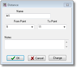
This Distance measure is different from the measures you’ve created in two ways. First, it’s calculated internally by the macro, instead of being entered by the user. In fact, the user of the macro never sees measurement M1. Second, when the macro runs, M1 is not calculated until this point—since it depends on Points 9 and 11, M1 has no meaning until they’ve been created. But once you create M1, it works just like any other measurement.
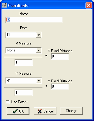
Now to create the true end of the dart on line 11 10, we will use the length M1 to position the point at the end of the dart:
Name |
12 |
From |
11 |
Y Measure |
M1 |
Y Scale |
1 |
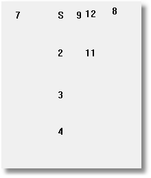
Again, compare your drawing to these two screen shots. The left shot shows the design window tightly minimized, while the one to the right shows a segment of the same window after scrolling in close with the mouse.
Create the left hip point (Point 13). The Hip Circ measurement is divided by 8; the negative Scale makes the point go to the left of Point 3 rather than to the right.
Remember, however, that since that resulting number needs to be made smaller (“subtract 2cm”), the point is moved back towards Point 3, which is in the positive direction. Thus, the X Fixed Distance is a positive “2.”
Name |
13 |
From |
3 |
X Measure |
Hip Circ |
X Scale |
-8 |
X Fixed |
2 |

Create the right hip point (Point 14).
Again we divide the Hip Circ by eight, but this time we are adding 2cm, so the X Fixed Distance is again a positive “2.”
Name |
14 |
From |
3 |
X Measure |
Hip Circ |
X Scale |
8 |
X Fixed |
2 |

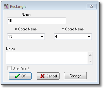
Drop straight down to create the crotch point (Point 15).
This is another Rectangle point type, because we are matching the X position (side-to-side) of one existing point and the Y position (up-and-down) of another existing point:
Name |
15 |
X-Coordinate |
13 |
Y-Coordinate |
4 |
Create the front crotch curve end point (Point 16).
This point uses the “X” measurement noted at the beginning of Leena’s drafting instructions.
X was supposed to be equal to Waist Circ divided by 20.
Since the Coordinate point type offers the Scale field, we can have MacroGen do this math for us automatically. The Scale of “-20” divides the Waist Circ by 20 and places the point to the left of Point 15. Again, a positive X Fixed Distance of “1” moves that point 1cm back toward Point 15.
Name |
16 |
From |
15 |
X Measure |
Hip Circ |
X Scale |
-20 |
X Fixed |
1 |

Create the left and right knee points (Points 17 and 18).
To measure to the left and subtract 1 (Point 17) the Scale is negative and the X Fixed Distance is positive.
To measure to the right and subtract 1 (Point 18), the Scale is positive and the X Fixed Distance is negative
Name |
17 |
From |
6 |
X Measure |
Knee Circ |
X Scale |
-4 |
X Fixed |
1 |

Name |
18 |
From |
6 |
X Measure |
Knee Circ |
X Scale |
4 |
X Fixed |
-1 |

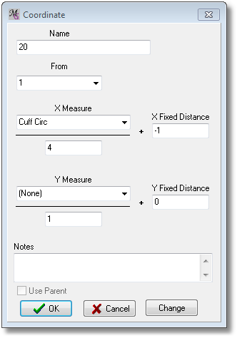
Create left and right cuff points (Points 19 and 20).
Use the same reasoning as above for the points to the left and to the right.
Name |
19 |
From |
1 |
X Measure |
Cuff Circ |
X Scale |
-4 |
X Fixed |
1 |

Name |
20 |
From |
1 |
X Measure |
Cuff Circ |
X Scale |
4 |
X Fixed |
-1 |
Create the point that will be the corner control point for the hip curve (Point 21).
In Tutorial 2, we learned that the key to connecting two lines (in this case the outside leg line and the waist line) with an arc is to position the corner point at the intersection of the two lines.
From the tabbed panel, select Point and Add, and then Line Line Intersect.
Select the start points and end points for each of the two lines:
Name |
21 |
Line 1 Start |
18 |
Line 1 End |
14 |
Line 2 Start |
7 |
Line 2 End |
S |

For the crotch curve, we first have to create a point that is perpendicular to the leg line. Since a perpendicular line forms a right angle, we can use the RIGHT ANGLE point type.
From the tabbed panel, select Point and Add, and then Right Angle.
Point 22 is at a right angle to the line formed by Points 17 and 16. The Distance field indicates how far away Point 22 will be from the line. In this case, it doesn’t matter what number you enter for the Distance. Point 22 doesn’t become part of the pattern; it is only used to define a line.
By checking the "C-Clockwise" box, we tell MacroGen in which of two possible directions to go when taking the perpendicular. In this case, it remains un-checked.
Name |
22 |
From |
17 |
Corner |
16 |
Distance |
5 |

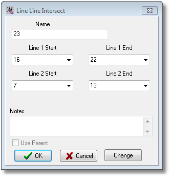
Now intersect the line from the waist center front (Points 7 and 13) with the line formed by Point 16 and the new Point 22:
Name |
23 |
Line 1 Start |
16 |
Line 1 End |
22 |
Line 2 Start |
7 |
Line 2 End |
13 |
All of the points:

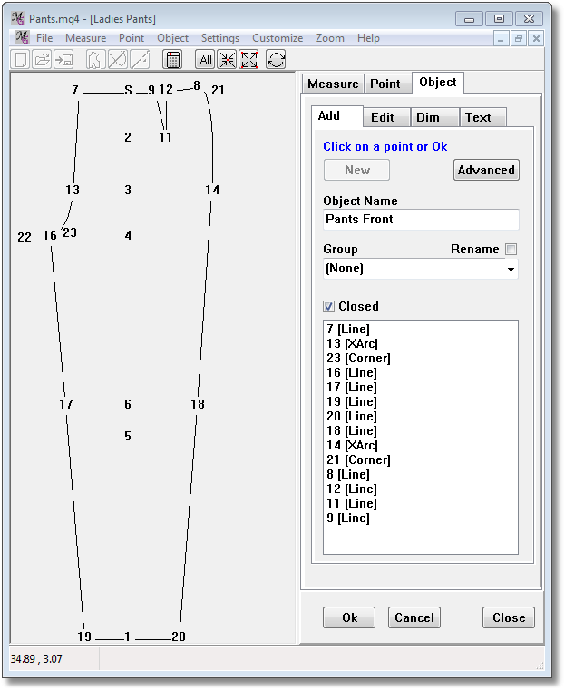
NEW OBJECT: CONNECT THE POINTS
Now that all the points have been entered, it’s time to connect the points and create the actual pattern piece.
From the tabbed panel, select Object and Add, and then click the New button. Each object must have a name. This is where you name the specific pattern pieces – in this case, the Pants Front. Type the name of the piece in the “Name” field at the top of the form. You learned how to add points to an object in Tutorial 1. Now that you have calculated all those points, what follows is easy. Follow your notes from Part A to connect all the points in the Pants Front:
7 |
Left Mouse (click with LM on point 7 on screen) |
13 |
Left Mouse Right Mouse PointType / XArc Start - OK |
23 |
Left Mouse (in list it becomes automatically a Corner point) |
16 |
Left Mouse |
17 |
Left Mouse |
19 |
Left Mouse |
20 |
Left Mouse |
18 |
Left Mouse |
14 |
Left Mouse Right Mouse PointType/XArc Start - OK |
21 |
Left Mouse (in list it becomes automatically a Corner point) |
8 |
Left Mouse |
12 |
Left Mouse |
11 |
Left Mouse |
9 |
Left Mouse |
Closed |
checked |
Click OK |
Now your drawing should look like this:
Congratulations! Click OK.
Note: In the list of points in the object you will see the following
Abbreviations: L = Line ) X = XArc Start C = XArc Corner *
Adding More Objects
According to your notes from Tutorial 2, you also need to create a zipper facing. Up to this point, every pattern you have seen has consisted of a single drawing object, but it’s perfectly legal to create more objects. First, though, we need to define some more points.
ENTER POINTS FOR ZIPPER FACING
Point 24 defines the top width of the zipper facing.
Name |
24 |
From |
7 |
X Measure |
(None) |
X Fixed |
-3 |

For Point 25 we get to use the CONTINUE point type for the first time. This point type is very handy. Once you feel comfortable with it, you’ll find it very helpful in a variety of situations. As explained in Tutorial 2, this point will lie on a line defined by two existing points (Points 7 and 13). Since we don’t know what the distance from 7 to 13 will be for any particular person, the only way to make sure that Point 25 is always 20cm away from Point 7 is to begin the “definition” of the line at Point 13, go up to Point 7, and then measure back down 20cm. This establishes the location for Point 25.
Add Point 25:
Name |
25 |
Start Point |
13 |
End Point |
7 |
X Measure |
(None) |
X Fixed |
-20 |
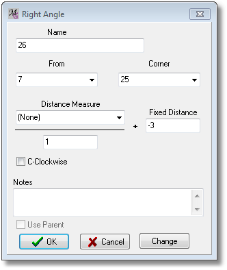
Point 26 establishes the bottom width of the zipper facing. We will use the RIGHT ANGLE point type again in this situation.
Name |
26 |
From |
7 |
Corner |
25 |
Distance |
-3 |
C-Clockwise |
not checked |
NEW OBJECT: CONNECT THE POINTS
Click the Object tab and the New button. Scroll in close so that you can see the upper left area. Enter a name for the facing and then connect the points:
Object Name |
Zipper Facing |
7 |
Left Mouse |
25 |
Left Mouse |
26 |
Left Mouse |
24 |
Left Mouse |
Closed: |
Checked |
Click OK. |
Here’s the zipper facing:

SAVE, CREATE AND TEST THE MACRO

Click the “Save” icon on the File toolbar or select “Save” from the File menu.
Give your macro a name, such as “Pants.mg4” and click the “Save” button. You can create sub folder if you want to save this file.
 Click “Create Macro” icon from the File toolbar, or select the “Create macro” from the File menu.
A macro is created from your Pants project to be tested and used in PatternMaker. It will be saved in the same folder as your mg4.file

You can test the macro in PatternMaker by clicking the Test Macro button, or select the “Test macro” from the File menu.
ADVANCED PRACTICE
Have the macro prompt for the zipper length. Create a prompted measurement called “Zipper Length” and then edit point 25 to use that Measurement rather than a Fixed Distance of 20.
Test the macro in PatternMaker and see if the zipper length is asked in the macro.